COMBINATIONAL LOGIC CIRUITS-MULTIPLEXER AND DEMULTIPLEXER
HELLO EVERYONE, WELCOME TO MY BLOG.
TODAY I AM GOIN TO SHOW YOU SOME QUICK NOTES FOR YOUR VIVA,PRACTICALS AND EXAMS.
TOPIC- MULTIPLEXER AND DEMULTIPLEXER
MULTIPLEXER-
INTRODUCTION
A multiplexer, also known as a data selector, is a device that selects between several analog or digital input signals and forwards the selected input to a single output line. The selection is directed a separate set of digital inputs known as select lines.
OR
A multiplexer is a circuit that accept many input but give only one output. The selection of a particular input line is controlled by a set of selection lines. Generally, there are 2n input lines and 'n' selection lines wose bit combination determine, wic input is selected.
A Block diagram of 4 to 1 line multiplexer is sown as follows:-

One of these 4 inputs will be connected to the output based on the combination of inputs present at these two selection lines. Truth table of 4x1 Multiplexer is shown below.
| Selection Lines | Output | |
|---|---|---|
| S1 | S0 | Y |
| 0 | 0 | I0 |
| 0 | 1 | I1 |
| 1 | 0 | I2 |
| 1 | 1 | I3 |
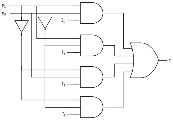
We can implement this Boolean function using Inverters, AND gates & OR gate. The circuit diagram of 4x1 multiplexer is shown in the following figure.
16x1 Multiplexer
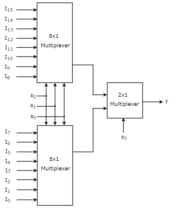
In this section, let us implement 16x1 Multiplexer using 8x1 Multiplexers and 2x1 Multiplexer. We know that 8x1 Multiplexer has 8 data inputs, 3 selection lines and one output. Whereas, 16x1 Multiplexer has 16 data inputs, 4 selection lines and one output.
So, we require two 8x1 Multiplexers in first stage in order to get the 16 data inputs. Since, each 8x1 Multiplexer produces one output, we require a 2x1 Multiplexer in second stage by considering the outputs of first stage as inputs and to produce the final output.
Let the 16x1 Multiplexer has sixteen data inputs I15 to I0, four selection lines s3 to s0 and one output Y. The Truth table of 16x1 Multiplexer is shown below.
| Selection Inputs | Output | |||
|---|---|---|---|---|
| S3 | S2 | S1 | S0 | Y |
| 0 | 0 | 0 | 0 | I0 |
| 0 | 0 | 0 | 1 | I1 |
| 0 | 0 | 1 | 0 | I2 |
| 0 | 0 | 1 | 1 | I3 |
| 0 | 1 | 0 | 0 | I4 |
| 0 | 1 | 0 | 1 | I5 |
| 0 | 1 | 1 | 0 | I6 |
| 0 | 1 | 1 | 1 | I7 |
| 1 | 0 | 0 | 0 | I8 |
| 1 | 0 | 0 | 1 | I9 |
| 1 | 0 | 1 | 0 | I10 |
| 1 | 0 | 1 | 1 | I11 |
| 1 | 1 | 0 | 0 | I12 |
| 1 | 1 | 0 | 1 | I13 |
| 1 | 1 | 1 | 0 | I14 |
| 1 | 1 | 1 | 1 | I15 |
We can implement 16x1 Multiplexer using lower order Multiplexers easily by considering the above Truth table. The block diagram of 16x1 Multiplexer is shown in the following figure.
Applications of Multiplexer:
Multiplexer are used in various fields where multiple data need to be transmitted using a single line. Following are some of the applications of multiplexers –
- Communication system – Communication system is a set of system that enable communication like transmission system, relay and tributary station, and communication network. The efficiency of communication system can be increased considerably using multiplexer. Multiplexer allow the process of transmitting different type of data such as audio, video at the same time using a single transmission line.
- Telephone network – In telephone network, multiple audio signals are integrated on a single line for transmission with the help of multiplexers. In this way, multiple audio signals can be isolated and eventually, the desire audio signals reach the intended recipients.
- Computer memory – Multiplexers are used to implement huge amount of memory into the computer, at the same time reduces the number of copper lines required to connect the memory to other parts of the computer circuit.
- Transmission from the computer system of a satellite – Multiplexer can be used for the transmission of data signals from the computer system of a satellite or spacecraft to the ground system using the GPS (Global Positioning System) satellites.
De-Multiplexer is a combinational circuit that performs the reverse operation of Multiplexer. It has single input, ‘n’ selection lines and maximum of 2n outputs. The input will be connected to one of these outputs based on the values of selection lines.
Since there are ‘n’ selection lines, there will be 2n possible combinations of zeros and ones. So, each combination can select only one output. De-Multiplexer is also called as De-Mux.
1x4 De-Multiplexer
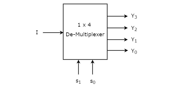
1x4 De-Multiplexer has one input I, two selection lines, s1 & s0 and four outputs Y3, Y2, Y1 &Y0. The block diagram of 1x4 De-Multiplexer is shown in the following figure.
The single input ‘I’ will be connected to one of the four outputs, Y3 to Y0 based on the values of selection lines s1 & s0. The Truth table of 1x4 De-Multiplexer is shown below.
| Selection Inputs | Outputs | ||||
|---|---|---|---|---|---|
| S1 | S0 | Y3 | Y2 | Y1 | Y0 |
| 0 | 0 | 0 | 0 | 0 | I |
| 0 | 1 | 0 | 0 | I | 0 |
| 1 | 0 | 0 | I | 0 | 0 |
| 1 | 1 | I | 0 | 0 | 0 |
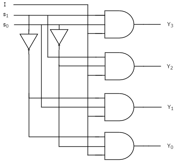
The circuit diagram of 1x4 De-Multiplexer is shown in the following figure.
Applications of Demultiplexer:
- Communication System – Communication system use multiplexer to carry multiple data like audio, video and other form of data using a single line for transmission. This process make the transmission easier. The demultiplexer receive the output signals of the multiplexer and converts them back to the original form of the data at the receiving end. The multiplexer and demultiplexer work together to carry out the process of transmission and reception of data in communication system.
- ALU (Arithmetic Logic Unit) – In an ALU circuit, the output of ALU can be stored in multiple registers or storage units with the help of demultiplexer. The output of ALU is fed as the data input to the demultiplexer. Each output of demultiplexer is connected to multiple register which can be stored in the registers.
- Serial to parallel converter – A serial to parallel converter is used for reconstructing parallel data from incoming serial data stream. In this technique, serial data from the incoming serial data stream is given as data input to the demultiplexer at the regular intervals. A counter is attach to the control input of the demultiplexer. This counter directs the data signal to the output of the demultiplexer where these data signals are stored. When all data signals have been stored, the output of the demultiplexer can be retrieved and read out in parallel.
1 : 8 demultiplexer
Similar to the 1 to 4 demux, 1-to-8 demultiplexer performs the transfer of single data to any one of the 8 possible outputs. It has 3 selection lines to distribute the data to the output.
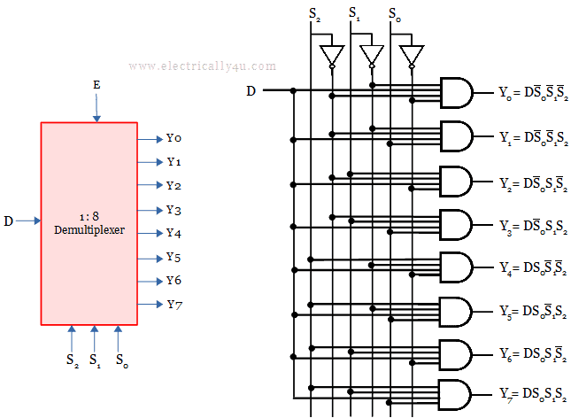
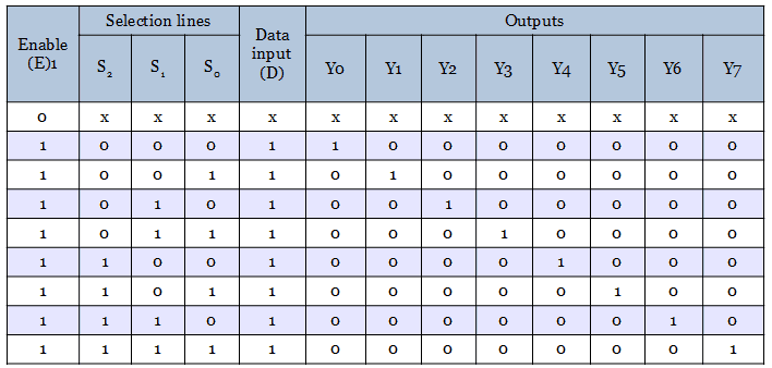
The operation is similar to a 1-to-4 demux. The following truth table or function table shows the operation of the 1-to-8 demultiplexer.

Comments
Post a Comment